
Reference parameter on the use of foam filters.
Necessary properties.
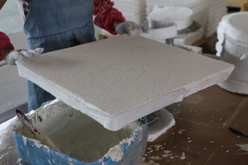
Obviously, the filter should effectively remove particles of inclusions, but not provide excessive resistance to metal flow. To work successfully, the filter must also withstand the thermal and mechanical stresses that occur during casting. The filter should not correlate due to metal-slag-filter interactions and should not corrode due to the forces acting on the filter during metal flow.
Types of filters.
Commercially available filters have either 1) direct pores with a constant cross section (honeycomb), or 2) connected pores with numerous changes in direction and cross section obtained by foaming. The third type of filter is funnel-shaped with narrow slots in the funnel-shaped body. The most commonly used refractory materials are alumina, zirconia, spinel zirconia, silicon carbide and mixtures of these materials.
Pore size (cells) and porosity.
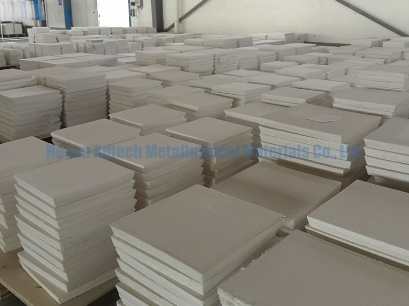
Cellular (porous) and ceramic foam filters are produced in a certain range of pore sizes. For cellular filters, the pore size is usually expressed as the ratio of cells per square inch. For foam filters, the pore size is usually expressed by the ratio of the number of pores crossed by a straight line – pores per inch.
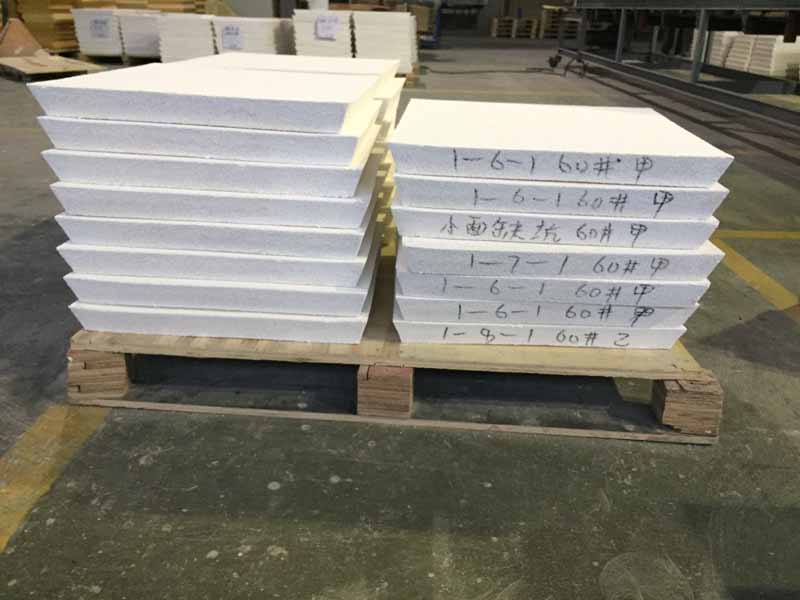
The pore size of extruded (extruded) filters typically ranges from 64 to 121 and 240 pores per square inch. For foam filters, the most common pore sizes are 10, 20, and 30 pores per inch. For iron and steel casting, larger pore sizes are preferred to provide sufficient mold filling speeds. Smaller pore sizes can be used when alloys are cast with very large overheating, and in investment casting, in which the filter is heated together with the mold.
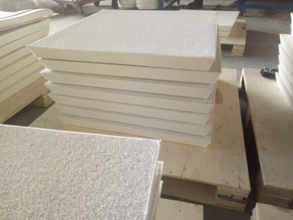
Actual pore sizes and surface area are quickly determined for pressed honeycomb filters. The geometry of the pore filters is incomparably more complex. Ceramic foam filters are rounded cells that are connected using several “windows”. The diameter of these cells determines the inner surface of the ceramic foam filter. The window size represents the diameter of the restriction channel for the passage of molten metal.
Filter placement.
Filters are placed horizontally in the imprint at the bottom of the mold, which allows molten metal to pass through the open surface of the filter. The metal quickly closes the filter surface, thereby reducing any thermal gradients in the filter structure. This system protects against shock, which would be the result of a flow of metal on the filter, reducing the likelihood of a filter failure.
Filters also work successfully in an upright position, although in this case they are more difficult to replace. Round filters are easier to fit vertically than square ones.
Related posts:
 Ceramic Foam Filters Sizing
 Aluminum Casting-Ceramic Foam Filters Sizing
 Foundry Foam Filters
 ceramic foam filters in the foundry
 Produce Alumina Ceramic Foam Filters
Ceramic foam filters used in aluminium casting
Ceramic foam filters for filtering the melt
Produce Alumina Ceramic Foam Filters
Ceramic foam filters used in aluminium casting
Ceramic foam filters for filtering the melt
 Aluminium Casting Filters
 Aluminum Casting-Alumina Foam Filters
 Aluminium Casting Honeycomb Ceramic Filter Parameter
Metallurgical and foundry filters for aluminum refining
Filtration of molten metal using ceramic filters
Aluminium Casting Honeycomb Ceramic Filter Parameter
Metallurgical and foundry filters for aluminum refining
Filtration of molten metal using ceramic filters
 Aluminum liquid filter
 Alumian Ceramic Foam Filters